
Milling machines‚ essential for metalworking‚ utilize rotating cutters to precisely remove material – a manual process demanding skill and careful setup for optimal results.
These versatile tools‚ dating back to the 19th century‚ remain vital for creating complex shapes and achieving tight tolerances in various manufacturing applications.
Understanding their operation and capabilities is crucial for machinists and engineers alike‚ ensuring efficient and accurate production of components.
What is a Milling Machine?
A milling machine is a foundational power tool used in subtractive manufacturing processes. Primarily‚ it employs rotating multi-point cutting tools to progressively remove material from a workpiece. Unlike drilling‚ which creates holes‚ milling excels at creating various shapes‚ slots‚ and profiles.
Manual milling machines require direct operator control over feed rates‚ speeds‚ and tool paths‚ demanding significant skill and precision. These machines are built around a rigid frame supporting a spindle that holds the cutter.
The workpiece is securely fastened to a worktable‚ which moves in multiple axes (X‚ Y‚ and Z) allowing for complex geometries. They are indispensable for prototyping‚ toolmaking‚ and low-volume production runs‚ offering flexibility and control.
Types of Milling Machines
Manual milling machines come in several configurations‚ each suited for specific tasks. Knee-and-column mills are the most common‚ offering versatility for general-purpose machining. Turret mills provide quick tool changes‚ ideal for repetitive operations.
Bed mills‚ with their larger table surfaces‚ are preferred for heavier workpieces. Horizontal milling machines utilize a horizontally oriented spindle‚ excellent for creating slots and pockets.
Vertical milling machines‚ conversely‚ have a vertically oriented spindle‚ suitable for profiling and surface work. Selecting the right type depends on the workpiece size‚ complexity‚ and production volume. Each requires a skilled operator for precise control.
Key Components of a Milling Machine
Essential components include the robust base‚ column‚ knee‚ spindle‚ and worktable‚ all working in harmony to deliver precise cutting action during manual operation.
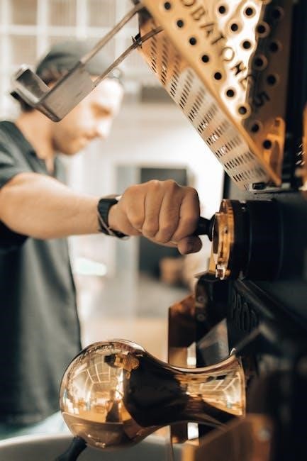
Spindle and Spindle Speed
The spindle is the heart of a manual milling machine‚ rotating to hold and drive the cutting tool. Its precision and rigidity are paramount for accurate machining. Spindle speed‚ measured in revolutions per minute (RPM)‚ significantly impacts the cutting process.
Lower speeds are generally used for harder materials and larger diameter cutters‚ while higher speeds suit softer materials and smaller tools; Selecting the correct speed prevents tool breakage and ensures a quality surface finish. Manual machines rely on stepped pulleys or gearboxes to adjust spindle speed‚ requiring the operator to carefully calculate the appropriate setting based on material‚ cutter type‚ and desired cutting parameters. Proper lubrication of the spindle bearings is also critical for smooth operation and longevity.
Worktable and its Movements
The worktable on a manual milling machine provides a stable platform for securing the workpiece. Crucially‚ it facilitates movement along three primary axes: X‚ Y‚ and Z. X-axis movement is typically longitudinal‚ Y-axis is transverse‚ and Z-axis controls vertical feed.
Manual machines utilize handwheels to control these movements‚ allowing the operator precise control over the cutter’s path. The table’s movements‚ combined with the spindle’s rotation‚ enable the creation of diverse shapes. Smooth and accurate table travel is essential for achieving desired dimensions and surface finishes. Regular cleaning and lubrication of the table’s ways are vital for maintaining precision and preventing binding.
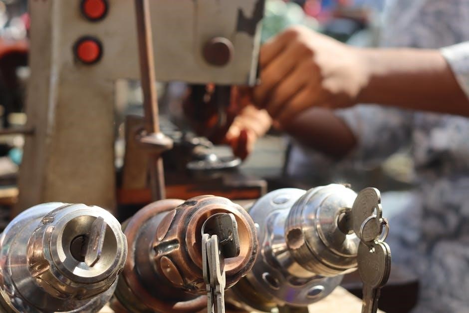
Cutting Tools for Milling
Cutting tools are paramount in milling operations‚ with various types suited for different materials and tasks. End mills‚ face mills‚ and slot drills are common choices for manual milling machines. High-speed steel (HSS) and carbide are prevalent materials‚ offering varying levels of hardness and wear resistance.
Selecting the correct tool geometry – including flute number‚ helix angle‚ and coating – is crucial for optimal performance. Proper tool sharpening is essential for maintaining cutting efficiency and surface finish. Securely mounting the cutting tool in the spindle‚ using a collet or chuck‚ is vital for safety and accuracy.

Operating a Milling Machine: A Step-by-Step Guide
Safe and precise operation requires meticulous setup‚ workpiece securing‚ parameter selection‚ and careful execution of the milling process – a skilled manual endeavor.
Setting Up the Milling Machine
Initial setup is paramount for accurate milling. Begin by thoroughly inspecting the machine for any damage or loose components‚ ensuring everything is clean and properly aligned. Next‚ mount the appropriate cutting tool securely in the spindle‚ verifying its concentricity and runout.
Carefully adjust the spindle speed based on the material being milled and the cutter type – referencing charts is crucial. Position the worktable at the desired starting point‚ utilizing the machine’s coordinate system for precision.
Double-check all clamps and locking mechanisms‚ guaranteeing a stable and rigid setup before initiating any cutting operations. Proper setup minimizes vibration and maximizes cutting efficiency.
Securing the Workpiece
Proper workpiece clamping is critical for safety and accuracy. Choose a suitable clamping method – vises‚ chucks‚ or specialized fixtures – based on the part’s geometry and size. Ensure the workpiece is firmly secured‚ resisting cutting forces during operation.
Avoid over-tightening‚ which can distort the part‚ and under-tightening‚ which leads to movement and potential hazards. Utilize parallels and supports to distribute clamping pressure evenly.
Always check for sufficient clearance between the cutting tool and the clamping devices‚ preventing collisions. A securely held workpiece minimizes vibration‚ improves surface finish‚ and ensures consistent results.
Selecting the Correct Cutting Parameters
Choosing appropriate cutting parameters – speed‚ feed‚ and depth of cut – is vital for efficient milling. Consider the workpiece material‚ cutter type‚ and machine capabilities. Higher speeds generally suit softer materials‚ while harder materials require slower speeds.
Feed rate dictates the cutter’s advancement per revolution; excessive feed causes chatter and tool breakage‚ while insufficient feed leads to rubbing and poor surface finish.
Depth of cut influences material removal rate; start with shallow cuts and gradually increase for optimal results. Consult machining charts and experience to determine the ideal settings.
Performing the Milling Operation
Initiate the milling operation by ensuring all safety guards are in place and the workpiece is securely clamped. Start the spindle and gradually engage the cutter with the workpiece‚ listening for any unusual noises or vibrations.
Maintain a consistent feed rate‚ applying even pressure to the machine’s controls. Monitor the cutting process closely‚ observing chip formation and surface finish.
Adjust feed and speed as needed to optimize performance and prevent tool damage. Regularly clear chips from the work area to maintain visibility and prevent interference.
Milling Techniques
Various milling techniques‚ like face and plain milling‚ offer diverse approaches to material removal‚ each suited for specific geometries and desired surface finishes.
Selecting the appropriate technique is crucial for achieving optimal results and maximizing machining efficiency.
Face Milling
Face milling is a fundamental technique employed on milling machines‚ primarily used to create flat‚ smooth surfaces on workpieces. This process utilizes a large-diameter cutter with multiple teeth to remove material across the entire surface area.
It’s commonly applied for squaring up stock‚ preparing surfaces for further machining‚ or achieving a precise final dimension. Both up-cut and down-cut variations exist‚ influencing chip evacuation and surface finish.
Proper cutter selection‚ feed rate‚ and depth of cut are vital for achieving optimal results and preventing chatter or excessive tool wear. Face milling is a cornerstone of many machining operations‚ providing a foundational surface for subsequent processes.
Effective face milling requires careful consideration of workpiece material and desired surface quality.
Plain Milling
Plain milling‚ a core milling operation‚ involves using a cylindrical cutter rotating on a horizontal axis to remove material from a workpiece. This technique is ideal for creating flat surfaces‚ slots‚ or keyways‚ offering versatility in shaping metal components.
The cutter’s diameter dictates the maximum width of the cut‚ and multiple passes may be necessary for wider features. Proper cutter selection‚ considering material and desired finish‚ is crucial.
Feed rate and depth of cut significantly impact the machining process‚ influencing surface quality and tool life. Plain milling is often a preparatory step for more complex machining operations‚ establishing a base surface for further refinement.
Careful setup and precise control are essential for achieving accurate results.
Slot Milling
Slot milling utilizes a side milling cutter to create grooves or channels – slots – in a workpiece. This process is fundamental for producing features like keyways‚ dadoes‚ and T-slots‚ essential for assembly and component integration.
The cutter’s width determines the slot’s width‚ and multiple passes can achieve wider slots. Climb milling or conventional milling techniques can be employed‚ each influencing cutting forces and surface finish.
Precise control of feed rate and depth of cut is vital to maintain slot accuracy and prevent cutter deflection. Proper workpiece clamping ensures stability during the machining process.
Slot milling demands careful planning and execution for optimal results.
Profile Milling
Profile milling involves machining a specific contour or shape onto a workpiece‚ replicating a desired profile with high accuracy. This technique is widely used for creating complex parts‚ molds‚ and dies‚ demanding precision and control.
Typically‚ a profile milling cutter‚ mirroring the desired shape‚ is employed. The machine follows a programmed path‚ carefully removing material to achieve the final profile.
Maintaining consistent cutting parameters‚ like speed and feed‚ is crucial for a smooth surface finish and accurate dimensions. Proper workpiece fixturing prevents vibration and ensures stability.
Profile milling requires skilled operation and careful attention to detail.
Milling Machine Maintenance
Regular maintenance ensures longevity and precision. Daily checks‚ weekly procedures‚ and long-term schedules are vital‚ alongside consistent lubrication of all machine parts.
Daily Maintenance Checks
Consistent daily checks are paramount for maintaining a milling machine’s optimal performance and preventing costly downtime. Begin each shift by visually inspecting all machine parts for any signs of wear‚ damage‚ or loose connections.
Specifically‚ examine the spindle for runout and listen for unusual noises during operation. Verify the coolant levels and ensure the system is functioning correctly‚ providing adequate lubrication and chip removal.
Clean the worktable and surrounding areas‚ removing any accumulated chips or debris. A clean workspace contributes to accuracy and safety. Finally‚ confirm that all safety guards and devices are in place and functioning as intended before commencing any milling operation.
Weekly Maintenance Procedures
Expanding on daily checks‚ weekly maintenance delves into more detailed inspections and servicing. Thoroughly lubricate all bare machine parts using an oil can‚ focusing on gears‚ slides‚ and lead screws to ensure smooth operation and minimize friction.
Inspect and tighten all fasteners‚ including those on the spindle‚ worktable‚ and guards. Check the drive belts for wear and tension‚ adjusting or replacing them as needed.
Clean the coolant tank and filter‚ replenishing with fresh coolant to maintain its effectiveness. Finally‚ examine the electrical connections for any signs of corrosion or damage‚ ensuring a safe and reliable power supply.
Long-Term Maintenance Schedules
Beyond weekly routines‚ long-term maintenance‚ scheduled every six to twelve months‚ involves comprehensive overhauls. This includes a detailed inspection of the spindle bearings‚ potentially requiring replacement or re-greasing by a qualified technician.
Examine the machine’s alignment‚ correcting any deviations to maintain accuracy. Inspect and potentially overhaul the hydraulic system‚ checking for leaks and replacing worn seals.
A complete cleaning of all internal components‚ removing accumulated chips and debris‚ is essential. Finally‚ a professional inspection of the electrical system ensures continued safe and reliable operation‚ extending the machine’s lifespan.
Lubrication of Milling Machine Parts
Consistent lubrication is paramount for a milling machine’s longevity and precision. Regularly oil bare machine parts using an oil can‚ focusing on sliding surfaces and joints to minimize friction and wear. Gears require specific gear oil‚ ensuring proper meshing and smooth operation.
The spindle‚ a critical component‚ demands high-quality spindle oil‚ changing it according to the manufacturer’s recommendations. Ways – the guiding surfaces – need specialized way oil to facilitate smooth table movement.
Always wipe away excess lubricant to prevent chip adhesion. Proper lubrication reduces heat buildup‚ extends component life‚ and maintains machining accuracy.
Troubleshooting Common Milling Machine Issues
Addressing issues like overheating‚ vibration‚ or tool breakage requires systematic diagnosis and correction‚ often involving lubrication‚ tightening‚ or tool replacement for continued operation.
Overheating Problems
Overheating in a milling machine can stem from several sources‚ demanding a methodical approach to diagnosis and resolution. Insufficient lubrication is a primary culprit; ensure all moving parts receive adequate oiling‚ as friction generates substantial heat.
Check the coolant system – if applicable – for proper function‚ verifying sufficient fluid levels and unobstructed flow. A clogged coolant system drastically reduces heat dissipation. Excessive spindle speed or feed rate for the material being cut also contributes to overheating.
Reduce these parameters and monitor the temperature. Finally‚ inspect bearings for wear or damage‚ as failing bearings create significant friction and heat. Regular maintenance and adherence to recommended operating procedures are vital preventative measures.
Vibration Issues
Excessive vibration during milling operations signals potential problems requiring immediate attention. A loose workpiece or inadequate clamping is a frequent cause; ensure secure fastening to the worktable. Check the cutting tool for damage – a dull or chipped cutter exacerbates vibration.
Imbalance in the spindle or rotating components can also induce vibrations. This often necessitates professional balancing. Verify the machine’s foundation is stable and level; an uneven surface transmits vibrations.
Inspect the machine’s structural integrity for any loose bolts or worn components. Reducing cutting speed or depth of cut can sometimes mitigate vibration until the root cause is addressed. Regular inspections and preventative maintenance are key.
Cutting Tool Breakage
Frequent cutting tool breakage indicates improper milling practices or machine issues. Aggressive cutting parameters – excessive feed rate or depth of cut – are common culprits. Reduce these parameters to alleviate stress on the tool. Ensure the correct tool material is selected for the workpiece material; mismatch leads to premature failure.
Insufficient coolant can cause overheating and tool fracture. Verify adequate coolant flow and concentration. Check for workpiece or tool runout‚ which introduces bending stress. A worn spindle bearing can also contribute to breakage.
Inspect the tool holding system for proper clamping and rigidity. Always use sharp‚ undamaged tools and follow recommended cutting speeds.
Safety Precautions for Milling Machine Operation
Prioritize safety: wear appropriate PPE‚ understand emergency stops‚ and practice safe cutting techniques to prevent injuries during manual milling machine operation.
Personal Protective Equipment (PPE)
Essential PPE is paramount when operating a manual milling machine‚ safeguarding against potential hazards. Safety glasses or a face shield are crucial‚ protecting eyes from flying chips and coolant spray.
Sturdy‚ closed-toe shoes prevent foot injuries from dropped materials or tools. Gloves‚ while sometimes used‚ require caution; avoid loose-fitting gloves that could become entangled in rotating parts.
Hearing protection‚ such as earplugs or earmuffs‚ is recommended due to the machine’s noise levels. Appropriate clothing‚ avoiding loose garments or jewelry‚ minimizes entanglement risks.
A shop coat provides an additional layer of protection against coolant and debris. Always inspect PPE for damage before each use‚ ensuring optimal safety during milling operations.
Emergency Stop Procedures
Immediate action is critical in a milling machine emergency. Familiarize yourself with the location of the emergency stop (E-stop) button – typically a large‚ red mushroom-shaped button – before operation.
In any unsafe situation‚ such as tool breakage‚ unexpected machine behavior‚ or personal injury‚ immediately press the E-stop button. This cuts power to the spindle and other moving parts.
Do not attempt to restart the machine until the issue is identified and resolved.
Report all incidents‚ even minor ones‚ to a supervisor. Know the location of the main power disconnect switch for complete shutdown if necessary. Regular drills practicing E-stop procedures enhance preparedness and ensure a swift response during real emergencies.
Safe Cutting Practices
Prioritize safety during all milling operations. Always secure the workpiece firmly using appropriate clamping methods‚ preventing movement during cutting. Never reach over or around a rotating cutter; use tools for adjustments.
Maintain a safe distance from the cutting area‚ and avoid loose clothing or jewelry that could become entangled. Proper chip control is essential – use brushes or compressed air (with eye protection) to remove chips‚ never hands.
Ensure adequate lighting and a clean work area. Avoid excessive cutting forces‚ which can lead to tool breakage or workpiece ejection. Always follow recommended cutting speeds and feeds.

Calculating Milling Costs
Accurate cost analysis involves factoring in hourly rates‚ fuel‚ and labor expenses‚ typically around $3.98/gallon for diesel and $51.24/hour for mechanics.
Hourly Rate Calculation
Determining an accurate hourly rate for milling operations is fundamental to profitability. This rate isn’t simply a guess; it’s a carefully calculated figure encompassing all ownership and operating costs. The formula generally involves dividing total monthly ownership costs by 176 hours – representing typical machine utilization.
Ownership costs include depreciation‚ insurance‚ taxes‚ and housing expenses. Operating costs‚ as previously noted‚ encompass elements like fuel (currently around $3.98 per gallon)‚ electricity‚ and the skilled labor of mechanics at approximately $51.24 per hour.
A precise calculation ensures projects are priced competitively yet profitably‚ covering all associated expenses and contributing to the long-term sustainability of the milling operation.
Unit Price Considerations (Fuel‚ Labor)
Accurate unit price assessment is critical when calculating the total cost of a milling operation. Fuel costs‚ currently averaging $3.98 per gallon‚ directly impact operational expenses‚ fluctuating with market conditions. Labor represents a significant portion‚ with skilled mechanics commanding around $51.24 per hour.
These costs aren’t static; they require regular review and adjustment. Furthermore‚ consider indirect labor – time spent on setup‚ tool changes‚ and quality control. Accurate tracking of these unit prices ensures realistic project budgeting.
Ignoring these details can lead to underestimation and reduced profitability‚ highlighting the importance of meticulous cost analysis in manual milling processes.

Advanced Milling Concepts
Transitioning from manual to CNC unlocks precision and automation‚ while toolpath programming dictates cutter movement‚ optimizing material removal and complex geometries.
CNC Milling vs. Manual Milling
CNC (Computer Numerical Control) milling represents a significant leap from traditional manual milling. Manual machines rely entirely on the operator’s skill and physical control to guide the cutting tool‚ demanding precision and experience for consistent results.
Conversely‚ CNC milling utilizes pre-programmed computer instructions to automate the entire process. This automation drastically increases speed‚ accuracy‚ and repeatability‚ especially for complex designs. While manual milling excels in one-off projects and quick adjustments‚ CNC shines in high-volume production runs.
CNC machines minimize human error and allow for intricate geometries unattainable by hand. However‚ they require initial programming expertise and can be less flexible for spontaneous changes compared to the direct control offered by manual operation.
Toolpath Programming Basics
Toolpath programming‚ essential for CNC milling‚ defines the precise route the cutting tool takes to create a desired shape. It begins with selecting a suitable cutting tool and defining the workpiece coordinate system. Programmers then input instructions using G-code‚ a standardized language understood by CNC controllers.
Basic commands control tool movement (X‚ Y‚ Z axes)‚ feed rates‚ spindle speed‚ and tool changes. More advanced techniques involve defining cutting strategies like roughing and finishing passes. Software often simulates the toolpath to identify potential collisions or inefficiencies before actual machining.
Understanding concepts like interpolation (linear‚ circular) and cutter compensation is crucial for generating accurate and efficient programs‚ ultimately translating design intent into a physical part.
Leave a Reply